
During our evolution a very efficient brain structure was developed in the human brain, to create an image from what we see. And therefore it is always very helpful to use a visual representation for abstract concepts, which we want to understand. We only can think using words, symbols or images anyway-
We will describe here a visual representation for paths in information networks, which we demonstrate at first with a 3-dimensional cube.
We use foll0wing method, to construct
a visual representation of paths,
which we can also use for cubes of any dimension and for any kind of information network. But we use at first only a 3 – dimensional cube, to demonstrate it.
- for labelling the 8 corners of the cube, we use the enumerating method, which we described in an earlier post. The 8 corners are enumerated with P0 to P7
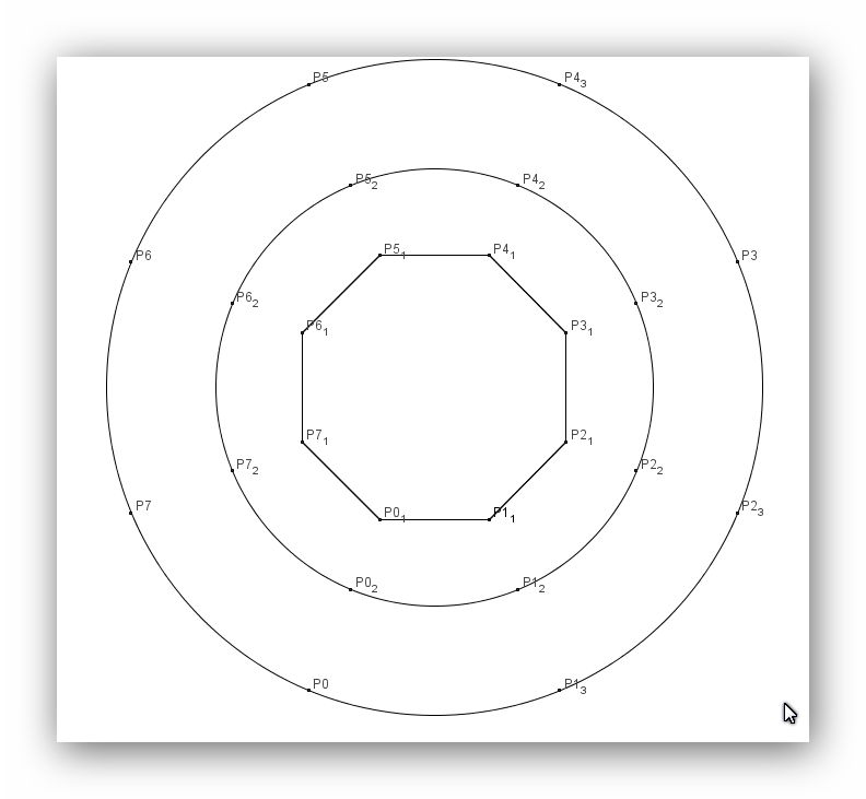
- at first we construct a regular polygon with 8 corners. The corner points on it represent the 8 corners of the cube. But the distance between 2 neighbour points on the polygon is not always the same.
- if both points are neighbour corners of the cube, they are connected by an edge with length 1
- if both points are diagonally opposite corner points of a square, then the distance between them is 1.414 and one of both points must be on the first circle
- if both points are diagonally opposite corner points in the cube, then one of them must be on the second circle
- then we construct a 1. circle, which represents the diagonals of the 6 square faces of the 3 dimensional cube
- thereafter we construct a 2. larger circle, which represents the space diagonals of the 3 – dimensional cube
- On the polygon and on both circles we arrange the 8 points in the same order. Same points are on the same radius from the midpoint to the outer circle.
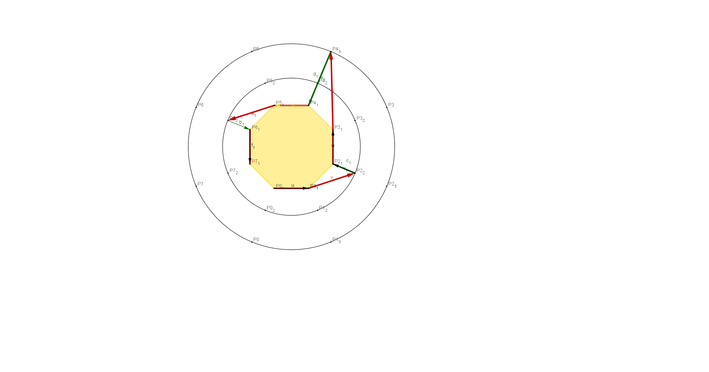
Construction of the path P0, P1,P2,P3,P4,P5,P6,P7
- We start with point P0, which is on the regular polygon.
- we use following convention: All starting points are always on the polygon
- To go from P0 to P1, we can keep going on the polygon, because this connection is an edge of length 1
- To go from P1 to P2, we have to use a diagonal in a square ( length 1.414) and therefore we go to P2 on the first circle.
- before we can go further to point P3, we have at first to go back to the polygon, because P2 and P3 are connected by an edge of length 1. We mark this by a green arrow, which has the length zero and therefore it would not matter, when we calculate the length of a path. ( of course, in the graphical representation a length is needed, but in the algebraic calculations we would give all green vectors the length zero )
- To go from point P3 to P4, we go from the polygon to the outer circle, because we have to use a space diagonal, which has the length 1,73
- We have again to go back to point P4 on the polygon, because P4 and P5 are connected by an edge of length 1
- From P5 to P6 we have to use a square diagonal and therefore we have to go to the first circle
- P6 and P7 are connected by an edge. Therefore we have at first to go back from the first circle to the polygon and then we can construct the connection between P6 and P7
- Because we use an open path, we do not go back to point P0
As usual, one has to use this kind of representation several times, to get familiar with it.
We can derive following from this representation:
- if two neighbour points in a path are on the polygon, then their distance is 1
- if one point is on the polygon and its neighbour point on the first circle, then the distance is 1.414
- if one point is on the polygon and its neighbour point on the second circle, then the distance is 1.73
- in a path always one neighbour point is on the polygon
With this representation we get a good overview of the structure of the paths in a cube of any dimension.
- for a cube of dimension n we have a polygon with n corner points and n-1 circles of increasing radii around it. On each circle the n corner points are arranged in the same order as on the polygon; all corner points with the same number are on the same radial ray.
To visually represent networks, which have no geometrical meaning, we just can give them a virtual geometric meaning:
- we construct a regular polygon. Direct neighbour points are connected by edges of length 1
- points, between which another point is, are on the first circle
- points, beween which there are 2 points, are on the second circle.
- etc.
For the radii of the circles we use suitable lengths, so that we get a nice representation.
The example with the cubes helped us, to find a good visual representation for paths in abstract information networks.
Of course, if there are many points in a network, then we can do all the work only with the help of computer programs. But now we know, what we have to program and we have examples, with which we can test the programs.
One further remark:
I prepared the drawings with GeoGebra, which is very good for it. One cannot create top quality pictures with it, which one could use for publications, but it is an excellent tool, to investigate geometrical problems.
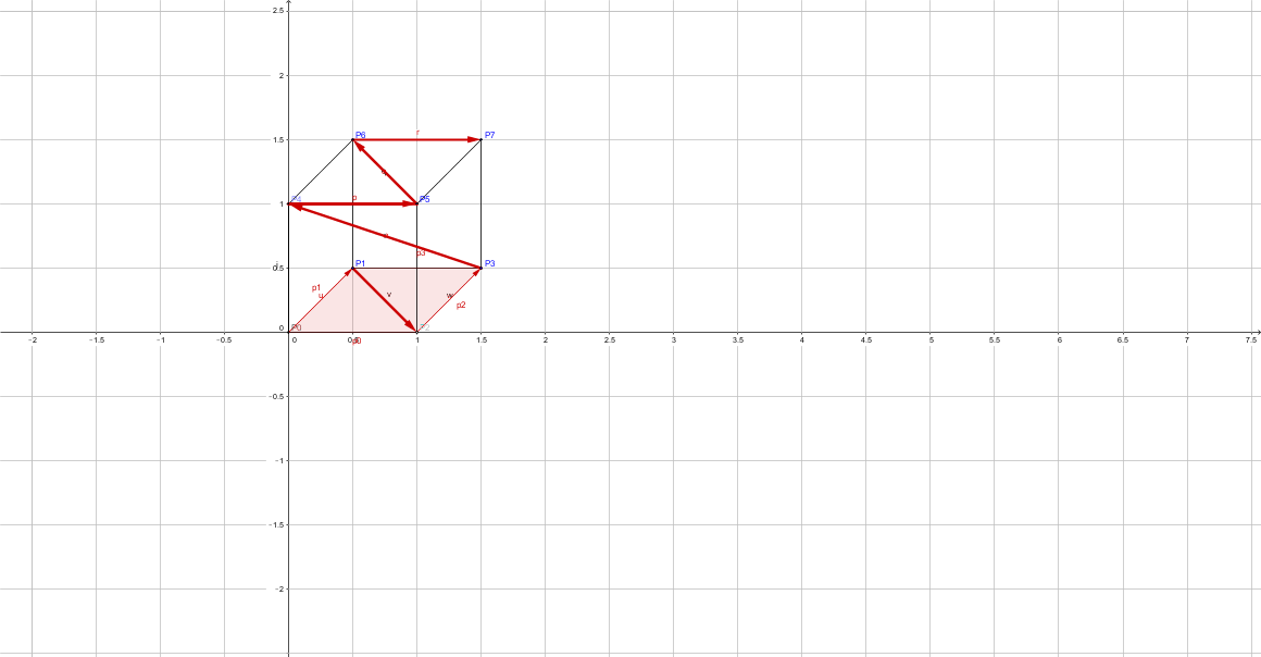
And here is finally the 3 dimensional cube with the path. I think, that even with a 3 dimensional cube, the abstract representation is better, because one sees directly all characteristics of a path.


Du muss angemeldet sein, um einen Kommentar zu veröffentlichen.